Are R and L Compatible? A Practical Guide to Resistor-Inductor Interactions
Explore whether resistors (R) and inductors (L) are compatible in typical circuits, with practical design tips, common pitfalls, and real-world use cases. Learn how to balance impedance, frequency response, and parasitics for reliable designs.

In electronics, resistors (R) and inductors (L) are generally compatible in many circuit designs, but they serve different roles and respond differently to signals. R dissipates energy as heat and sets current levels, while L stores magnetic energy and introduces reactance that increases with frequency. The key to are r and l compatible is to pair them with a clear impedance budget, match frequency response, and account for parasitics so they work together toward the circuit’s goals.
Are R and L Compatible in Circuit Design?
Are R and L compatible? The short answer is yes in many common designs, but success depends on context. Resistors (R) and inductors (L) play distinct roles: R governs steady-state current and dissipation, while L shapes transient response and voltage across the winding. The My Compatibility team emphasizes that are r and l compatible is not a single property but a relationship that shifts with frequency, load, and layout. Understanding this relationship helps you predict how a circuit will respond from DC through the audible or RF bands. When you design with this mindset, you can avoid common missteps and build more robust systems.
- Are r and l compatible is a contextual question that depends on frequency, load, and layout.
Comparison
| Feature | R-first design | L-first design |
|---|---|---|
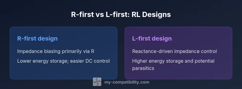
| Dominant impedance behavior | Resistor-dominant at target DC/low-frequency range with minimal phase shift | Inductor-dominant in mid-to-high frequencies with larger phase shift and reactive energy storage |
| DC behavior | Straightforward current control with no energy storage | Energy storage is inherent; DC paths may saturate if not biased properly |
| Size and cost considerations | Typically smaller, cheaper per component for simple networks | Inductors can be larger and more expensive at matching power levels |
| Best for | Low-frequency biasing, simple passives, and temperature-stable networks | High-frequency signal shaping, filters, and impedance tuning |
| Risk and parasitics | Lower parasitic sensitivity in simple RC-like roles | Magnetic coupling, core saturation, and parasitics require careful layout |
| Integration with other elements | Easier with capacitive and resistive combinations | Requires careful routing to minimize EMI and stray inductance |
Positives
- Clarifies when to prioritize resistance vs inductance based on frequency and load
- Guides cost-effective and size-conscious designs without sacrificing performance
- Improves signal integrity by aligning impedance goals with real-world parasitics
- Supports robust design decisions across common circuit families
Cons
- May oversimplify RL interactions in highly complex nets with multiple reactive elements
- Requires thorough layout and testing to manage parasitics and EMI
- Design decisions can be iterative and time-consuming in sensitive applications
R-first or L-first can be the right choice depending on your circuit goals
Choose R-first when DC bias and power dissipation are the priority. Choose L-first when you need precise frequency shaping and impedance control at higher frequencies. In practice, most real designs balance both aspects for reliable performance.
Questions & Answers
Are resistors and inductors directly compatible in a circuit, or do they require special considerations?
They are generally compatible, but you must account for how each part behaves across frequency. Resistors provide steady-state current control and heat dissipation, while inductors introduce reactance that grows with frequency and store energy magnetically. The key is to design for the combined impedance and to manage parasitics such as winding capacitance and PCB inductance.
They usually work together, but you have to plan how their different reactions to frequency affect the circuit.
How does frequency affect the interaction between R and L?
Frequency determines the relative impedance contribution of each element. At low frequencies, resistors dominate the impedance; at higher frequencies, inductors contribute more, increasing phase shift and potential resonance. Designing for a target bandwidth helps ensure R and L cooperate rather than fight each other.
Frequency decides who leads the impedance—R at low frequencies, L as frequency climbs.
What steps should I take to decide whether to prioritize R or L in a design?
Start with a clear impedance budget and identify the required phase response. Assess voltage and current limits, DC bias, and the desired signal shape. Then select R to meet bias and loss requirements and choose L to achieve the needed reactance at the operating frequencies. Finally, verify with simulations and measurements.
Define goals, budget impedance, pick R for bias, pick L for reactance, then test.
Can I use R and L together without a capacitor in a frequency-selective network?
Yes, you can build RL networks that act as first-order filters or impedance matching elements without capacitors, though the lack of a capacitor changes the frequency response and may limit certain filter types. Expect a different slope and cutoff behavior compared with RC or RLC networks.
You can, but the response will differ from capacitor-inclusive designs.
What common mistakes should I avoid when combining R and L?
Overlooking parasitics, underestimating coil saturation, and ignoring PCB layout can skew results. R and L values chosen independently of the rest of the network may cause unexpected resonances or impedance mismatches. Always validate with real-world testing.
Watch out for parasitics and layout, and test with real signals.
Where can I learn more about RL circuits and practical synthesis?
Many electronics textbooks and reputable tutorials cover RL circuits and practical design methods. Look for resources on impedance, RL filters, and circuit simulation to deepen understanding and bridge theory and practice.
Check standard electronics textbooks and reputable online tutorials.
Highlights
- Define the target frequency range before choosing either component
- Use an impedance budget to steer R and L decisions
- Account for parasitics and layout early in the design
- Test under real-world signal conditions to validate assumptions
- Consider RL interactions in filters and timing-critical circuits
- Evaluate cost and size implications alongside performance